What a strange time. As the year comes to an end, and I’m ready to move once again and start a new chapter of my life, I get to roll vicariously in the stress of my final projects. It is as such I am pleased to be creating the last component of the final project of my undergraduate career. It’s also fitting that this project exploded from the linear algebra library I wrote during winter break of my freshman year.
I can’t exactly tell you what this project has taught me. Over time I’ve used it as a context to learn everything from math to mechanics and overything in between. But most of all, it’s taught me that working hard at something and dedicating time to a project really does pay off. And it’s given me the confidence to foolishly believe I can accomplish just about any thing if I try hard enough for long enough.
Undoubtably this semester it’s taught me everything I could have possibly dreamt of knowing about optics, materials, imaging science, and integrating over the universe. Most of my game development professors and peers haven’t seen my work yet, but I sure hope I get a chance to show them before I leave– especially the ones who saw the beginning of my game engine three years ago.
Well anyway, enough reminiscing, here is a link to the well needed project documentation:
Project Documentation Link
My final project in my Physical Computing and Alternative Interfaces course required me to have 2 devices communicating. I tried to do this with my PIC16F1829 chip but found that there were no libraries available for both my chip and the compiler I was using for inter-device communication. However, I looked in the data sheet and found that there was hardware available for I2C communication.
The I2C protocol is a 2 wire single master multi slave asynchronous protocol. One of the wires serves as a clock, while the other transmits data. Using an open-drain design, the two wires go from one device to another, with a pullup resistor in between ensuring the default state of each line is a logical one. The general pipeline for using I2C is as follows:
1) The master transmits the address of the slave it wishes to communicate with & whether the master wants to send or recieve data.
2) The called slave responds
3) The master transmits / recieves the payload of the message
These of course are very general steps which can be expanded:
In step 1, the master first initializes communication by sending a start bit. Once the slaves recieve a start bit, they begin paying attention because the master might ask for their address. After the start bit, each bit of the 7 bit address is sent one at a time. The process for sending each individual bit will be outlined at the end of this section. Finally, after the 7 bit address is sent, a single bit indicating whether the master wishes to recieve or transmit is sent.
After each byte sent, regardless if it is the first byte containing a slave address, or a byte containing part of the message payload, a slave must send an ACK / NACK bit. The ACK / NACK bit is an acknlowedgement bit which is always sent as the 9th bit of a message (excluding start / continue bits) and indicates that everything is going according to plan on the recieving end. On the first byte of communication, containing a start bit and the slave address, all slaves respond with a NACK bit if they are not being called, and an ACK bit if the address belongs to them. While it may seem unintuitive that we could send two messages along the same line at once, this is made possible by the pullup resistors which we will discuss the implications of in a later section.
After each ACK/NACK bit, the master sends a continue / stop bit indicating that the master either still wants to communicate, or is finished. After recieving a NACK bit from a slave, or sending a NACK bit to a slave, a stop bit will almost always follow.
As made evident, there are many different “kinds” of bits which can be sent. Each of these is very precisely defined as follows:
1) Start Bit - Sent by pulling the Data line low while the Clock line floats high (must follow a stop bit).
2) Stop Bit - Sent by releasing the Data line while the Clock line floats high.
3) Continue Bit - The same as a Start bit, but comes after an acknowledgement bit.
These special kinds of control bits are the only times where the Data line may change while the Clock line is high. When sending any other kind of bit the Clock line serves as a mutex of sorts (for the rest of you software people).
The process is the same for ACK bits, NACK bits, and bits belonging to the payload of the message:
1) First the Clock line is pulled low. This indicates to the recieving party that the transmitting party has begun to load a bit into the Data line.
2) While the Clock line is low, the Data line is set to the appropriate value of the data (1 for ACK, 0 for NACK).
3) Once the Data line is set appropriately, the Clock line is released and allowed to float indicating to the reciever that the bit is loaded and ready to be read. At this point, the transmitter waits a minimum amount of time (4 microseconds for standard I2C) to ensure the reciever has time to read the data.
One of the great consequences of this setup is the inherent flow control mechanisms given to the slave devices. Because the default state of the Data and Clock lines are a logical one, if two devices are trying to control a line at the same time, and one device pulls the line low while the other lets it float, the resulting line will be pulled low. One of the devices realizes that the line has a different value than it expected, and realizes another device must be using the line– and stops transmitting on it. This process is known as Clock Stretching when utilized by slave devices, or Arbitration when exploited by master devices.
After researching and understanding this protocol I tried to use the datasheet for my PIC16F1829 chip to utilize the on-chip hardware to send and recieve data using I2C. Unfortunately this effort was met with failure from every direction. Additionally, there were no examples for using those features of the chip available online or in the starter kit documentation which I own.
Out of luck, I decided things tend to break less if I create them myself. As such, I wrote my own adaptation of the I2C protocol. It is essentially equivalent, except it uses 4 wires, where each device has recieving Data and Clock lines as well as transmitting Data and Clock lines. Other than that, the protocol really remains nearly identical.
After I wrote this lightweight I2C library to use on my chips, I had to come up with a simple application to use it (and test it)! I decided to connect two of my PIC16F1829 chips via my 4 wire adaptation. The master waits for a series of 25 button presses, recording the time intervals between each press. The master then encodes this data, and sends it to the slave. After recieving all of the data, the slave then plays back the sequence by flashing an LED light for each button press.
This simple project caused me quite a bit of strife. Trying to keep track of the state of two separate devices using only 2 bits (the recieving and transmitting clocks) for flow control was very difficult. A lot of mistakes were made on my part dealing with concurrency on such a low level, but I was able to debug and work through all of them.
By the time I actually got this project working I had less than a day to try to make it as presentable as possible. I determined that if no action is taken for too long, the device should do something akin to a “screensaver mode”. I decided it would be fun if I created a morse code lookup table, this way actual messages can be transmitted and read as morse code through a blinking LED.. Not very practical- but cute none the less. As of now, after a minute of inactivity, the master device (Emit is his name) says “I love you” in morse code to the slave device (known as sally).
Sally never responds.
I would put the code up for this assignment, but it is 4 files and spans several hundred lines of low level chip specific code. Over the next few days I will find an appropriate format to host the code (Perhaps github), but if I just dumped it here it would be essentially useless to everybody.
Additionally, here is a video of the project working:
Video Link
Update:
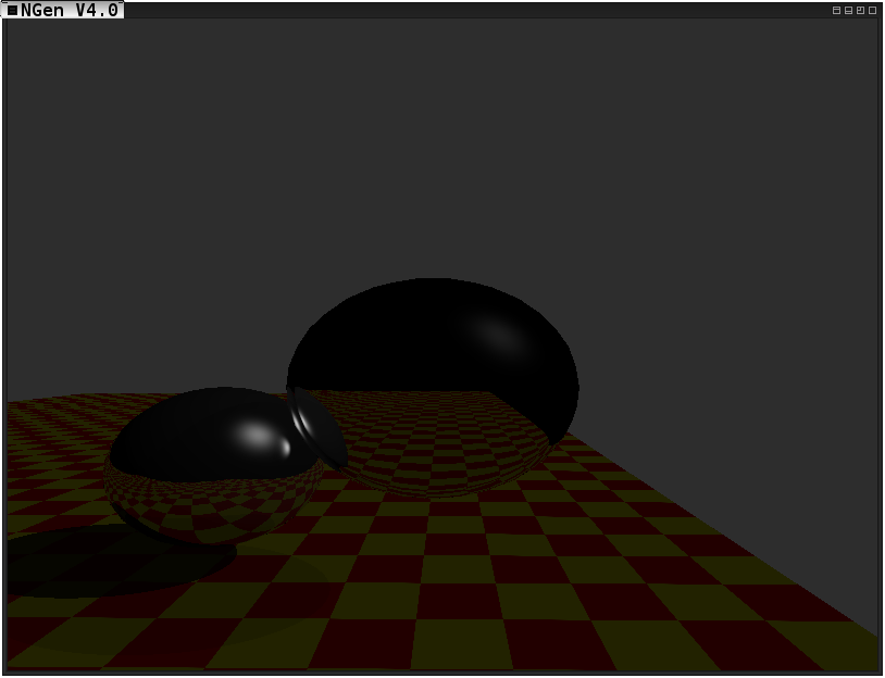
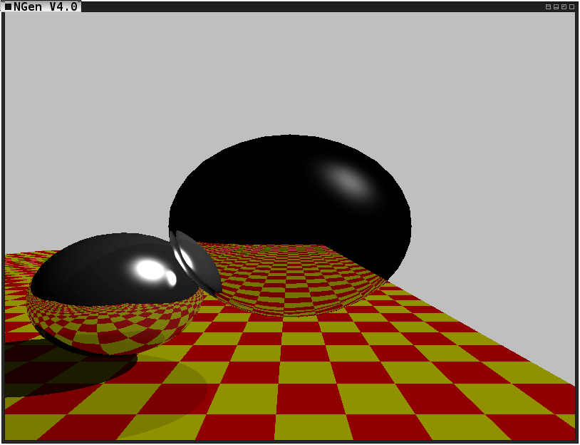
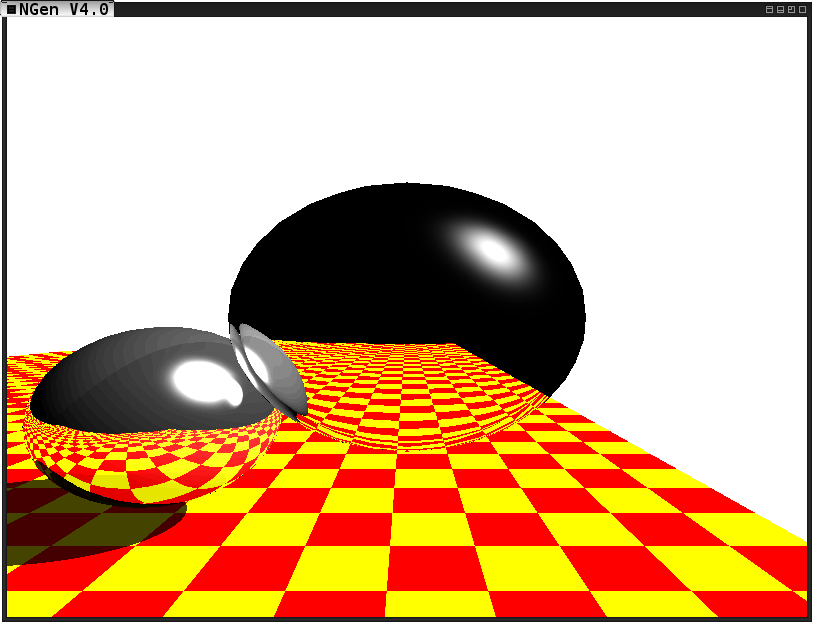
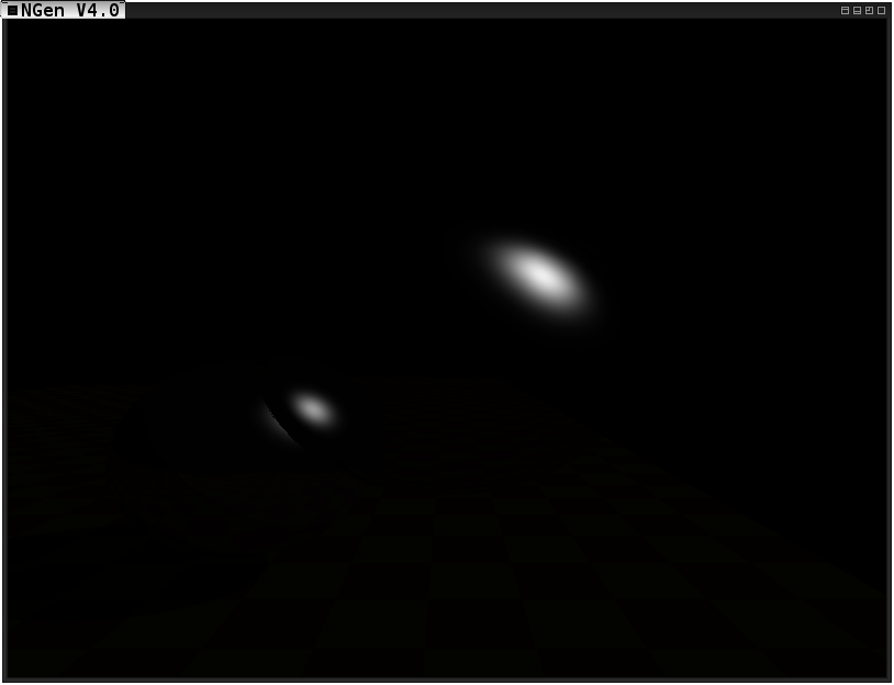
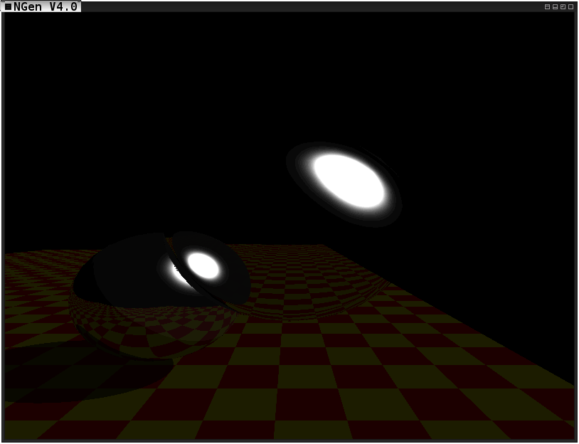
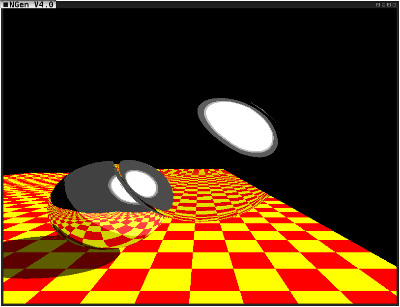
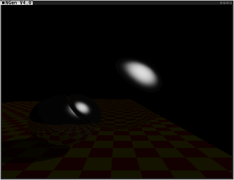
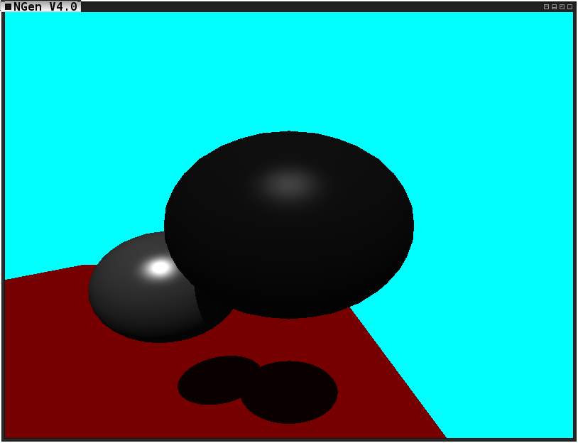
Turns out, nothing was wrong with my Tone Reproduction. I needed to remove ambient light & change the background color so it doesn’t skew the average scene luminence as much. Here are some images with those simple changes made to the scene:
Ward @ 10 nitsWard @ 100 nitsWard @ 1000 nits
As the semester comes to an end our last assignment is due: Tone Reproduction. For this assignment we had to use both Ward and Reinhard tone reproduction to generate an image with various different lighting conditions. The actual lighting of the scene does not change, but the tone reproduction and maximum illumination of the scene does, changing the way the scene luminences are compressed to RGB values. Unfortunately, due to course work I really had to rush this assignment, which is unfortunate because tone reproduction seems like a vital step in recreating realistic scenes. Furthermore, I believe some very immersive visual effects can be generated in games by using Reinhard tone reproduction and mapping the average luminence of the 8x8 block of pixels in the center of the screen to middle grey. In a dynamic scene this could cause some very interesting percieved changes in a scene by what the user is focused on. But this will all need to take place at some later date, because I just don’t have the time this finals week.
I probably should have adjusted the scenes light intensity because the pictures came out a little dark. They seemed to appear a bit brighter when being displayed live, maybe just an illusion due to the constant refreshing.
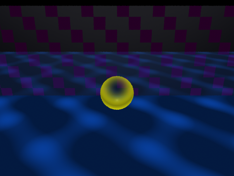
I was given a design challenge on Friday in my Physical Computing and Alternative Interfaces class. I needed to design a game which uses one or more of the following as the primary materials: spandex, dried beans, plush bats, yarn, cabbages, lab chairs, padlocks, magnifying glass, or paper clips. Also fairly recently was the advent of gravitational waves! And finally, my game which uses Spandex and Yarn:
In a world where humans and aliens have both harnessed the power of gravity, we must clash in the most epic of wars! With the firm and ignorant belief that the universe is not big enough for the two species, we terrible humans are trying to hurl the aliens world into the black hole at the center of our galexy! And of course, they are trying to stop that from happening.
The game is played with a large stretched square of spandex suspended ~4 feet off of the ground. The spandex has strings of yarn connected to it from both the top and bottom in a total of 16 places (8 unique connection points from both the top and the bottom), a ball, and eight 3 way switches on opposite sides.
When the switch is pulled either up or down, a motor will pull one of the pieces of yarn which is connected to the top or bottom of the spandex respectively. If your opponents corresponding switch is in the direction opposite yours, the spandex will return to equilibrium at that point.
At the start of the game, the alien’s planet is dropped into the middle of the spandex, representing the fabric of spacetime. The two players then flip switches trying to get the planet to roll off of the opposite side of the spandex!
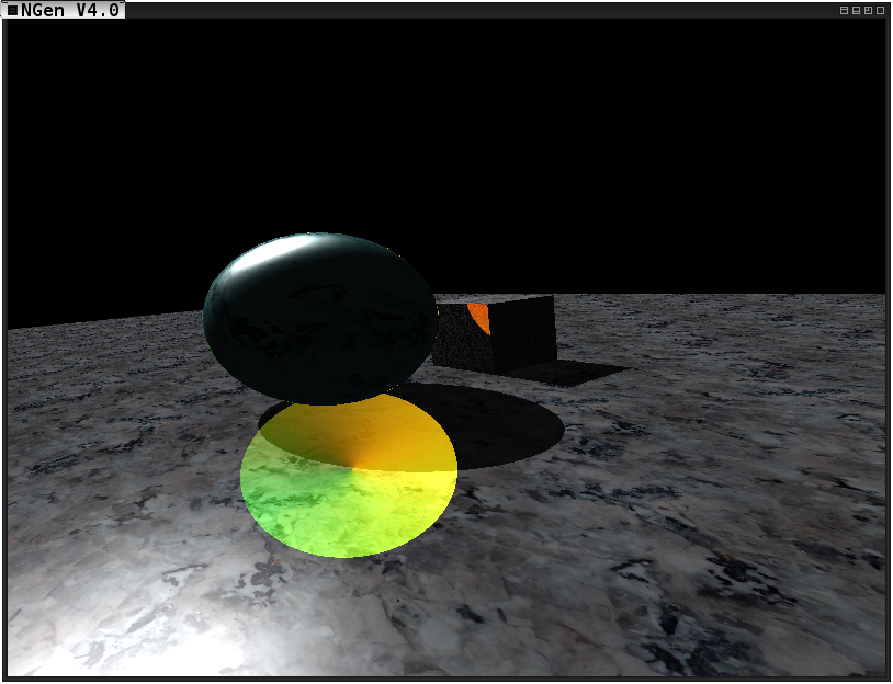
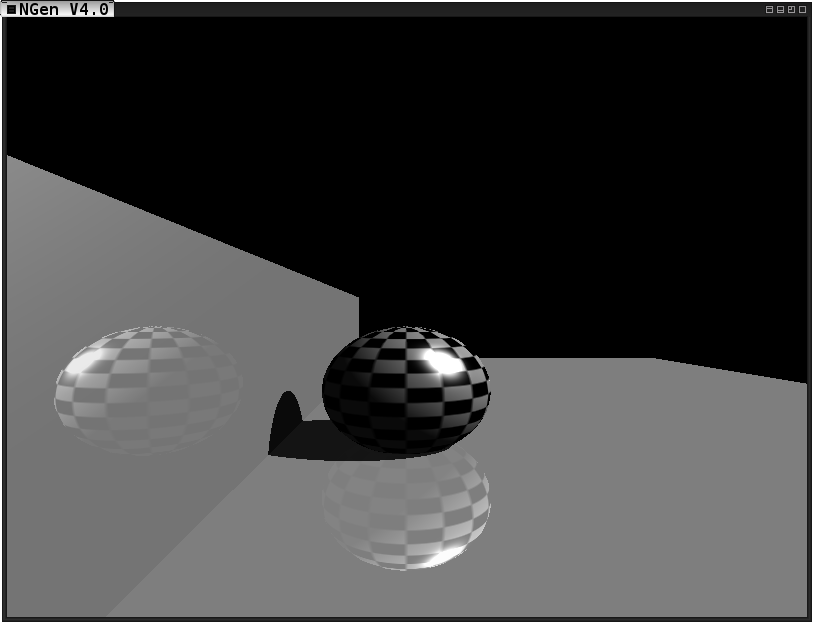
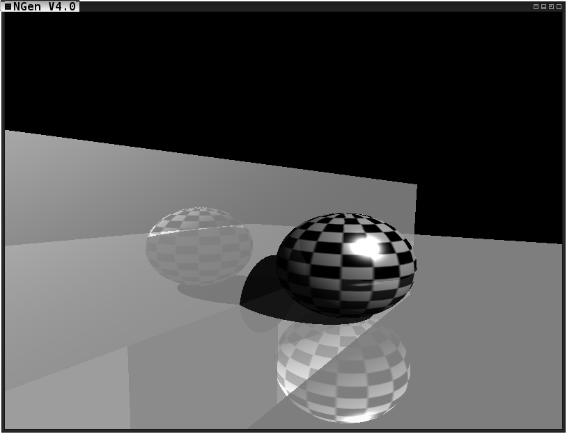
I write this post with extreme pride and minor disappointment. It is my displeasure to say I did not fully complete the latest assignment in my Global Illumination class in time. However, I solved all of my problems and in a few more hours of work it should be well all done! This is what I currently have complete:
The incomplete image featuring both reflective and transmissive materials
As you can see, all of the trickiest things are working. Total internal reflection is detected (but not resolved yet), and I need to disregard (or mitigate) the shadows due to transmissive surfaces which should not be that hard either! I have to say, I am really amazed at the images I have been capable of generating throughout this semester. Although I’ve really been struggling to keep up with this course, and dedicating ~18 hours of work a day for the last 6 days straight (plus more casual work before that)– I have to say I’ve learned more in this course than any other course since enrolling at Rochester Institute of Technology.
The knowledge I’ve gathered makes all of the stress & strain worth it by far– and I couldn’t be more proud to have minorly failed this assignment, because I’ve already come further in my graphics programming knowledge than I ever expected.
In my Global Illumination course, we had the opportunity to utilize Pixar’s Renderman Shader Language, and prman for a project, if we so desired. I did choose to do this! The project was, given the following scene:
The original image given as a base for the project
I first had to modify all of the shaders to produce a distinctly different output:
My modified version of the scene
Next, I had to replace the shaders entirely with my own:
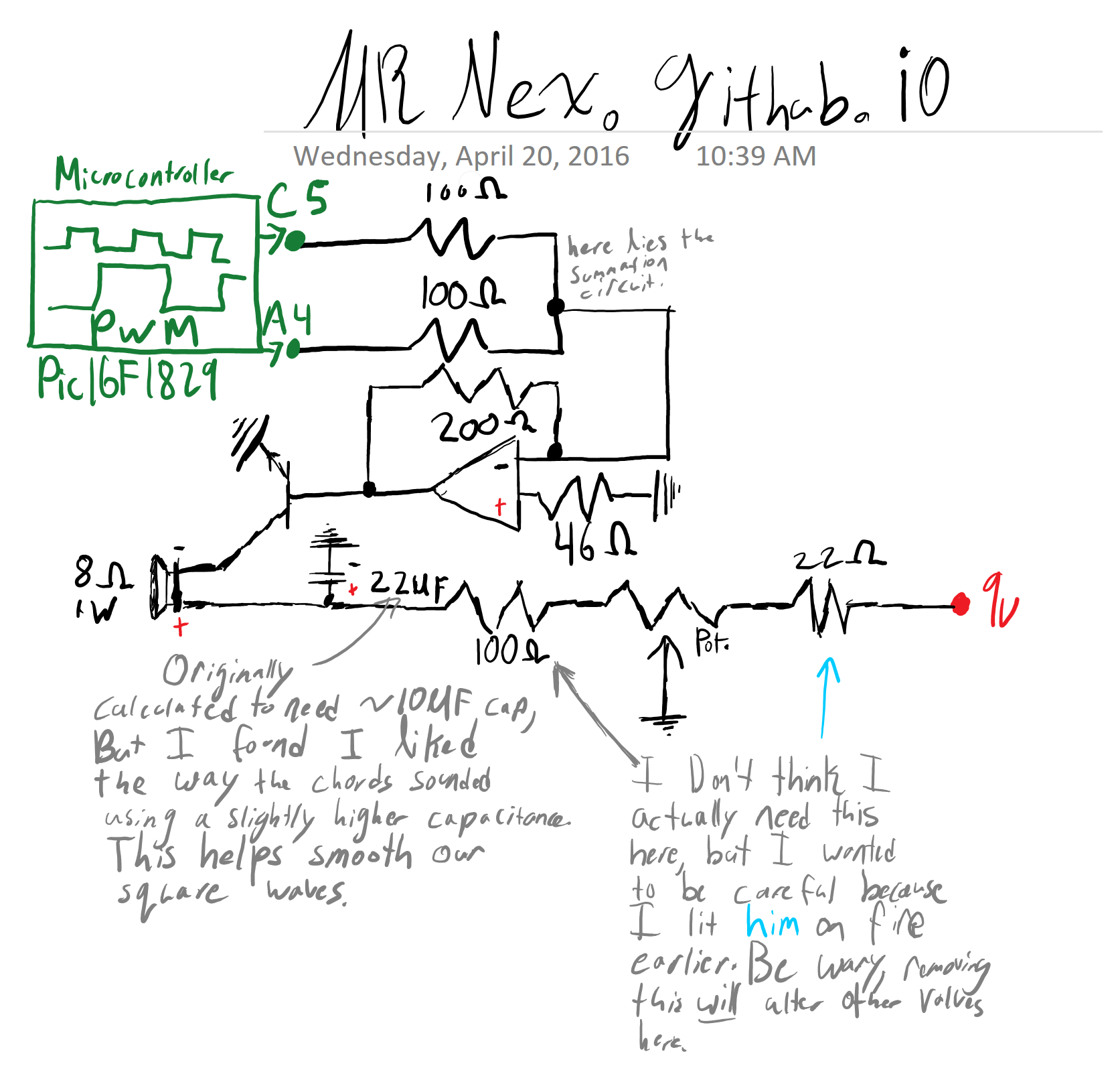
As I believe I mentioned in here, the last project we got assigned in my Physical Computing and Alternative Interfaces class was to do something involving audio. I wanted to continue the instrument I was building onto a pair of gloves (without the fussyness of trying to put it on a glove). So I did! The instrument is played with 10 force sensitive resistors, which you press using your fingers. Each hand controls a set of 32 distinct tones, allowing you to play any two tones simultaneously for a total of 1024 combinations. One set of FSRs produces tones which are an octave higher than the other. The instrument was originally created with playing walking basslines with complex melodies over it. The way this is done, is by having the FSRs act as a 5 digit binary number, which is the number of semitones in an equal tempered scale above a root frequency. This means that not only will putting down a finger result in a change in tone, but lifting up a finger will also change the tone leading to interesting and fast paced patterns. Further more, it allows the artist to jump around between octaves with ease (simply by placing down the pinky will jump 16 “keys” or tones)- a style which I think is demonstrated well through one of Bobby Mcferrin’s Performances.
The tones are generated through two separate PWM outputs, which are then added together through a summation circuit. The waveforms then use a transistor to pull a more powerful current with a voltage of 9 volts, in the same waveform. I then send this through a lo pass filter to help smooth the square waves, resulting in triangle waves. These then drive the speaker at the desired frequency.
Below you can see the circuit:
I had a lot of fun with this assignment. Eventually I stopped working on it because every time I took it out I would just end up playing songs that I could translate from my background playing piano or my small knowledge of music theory. Some features I did include that I was very happy with is the ability to tune the instrument to both the chromatic or harmonic scales (and the code for pentatonic, or similar, would be trivial). This allows the instrument to be given to somebody with no musical background and them easily be able to play in tune. While others, who understand the strange combination of music theory / temperment and binary needed to play the instrument properly, can perform more elaborate pieces including dissonance, key changes, and more.
Here is the code for a PIC16F1829 microcontroller to drive the circuit above:
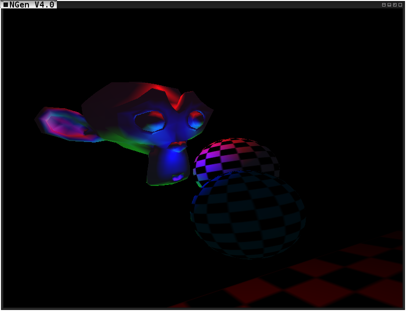
I am way to tired- so this one will be kept short. This assignment posed a lot of challenges. I found that the architecture of my game engine was not ready for a parallelized reflection pass. This caused me to need to build a mildly makeshift foundation that will serve as the skeleton for a more robust implementation later on. This turned out to me way more work than I bargained for, but I got it done. I’ve been awake for a collective 60 hours over the last 3 days, and so I was too tired to revert my scene back to the original Whitter image before I go to take a nap. Here are some images of various stages of progress, aswell as one final image depicting the working reflections:
Mapping texture coordinates to reflectionsNot quite correctShaded reflections from sphere on the boxesAdding reflections from boxes on sphere, and boxes on boxes, but there is Z-fighting between reflectionsNo more Z-Fighting, but we lost a sphere! I love how you can see the edges of the platform behind the camera in the reflections on the sphere here.A final image, exhibiting the working reflections-- just not in the whitted scene. Two boxes and one sphere instead of visa versa!
Last week marked the end of Project 2 in my Alternative Interfaces and Physical Computing course. For our second project we had to create a wearable interactive experience for users. I decided that I wanted to try to create an instrument!
My thought was that I can connect 5 force sensative resistors to a glove, reading an analog input from each one. Then, representing the 5 fingers as a 5 digit binary number, N. N, now represents the number of halfsteps above the root note the instrument is tuned (or programmed) to using an approximation of the traditional 12 intervals used in western music theory. I use an equal temperment system, a compromise of a just temperment system where each of the 12 tones within one octave can be found by multiplying the closest member of the same harmonic series with the ratio of two whole numbers. The difference between an equal temperment system and a just temperment system is that a just temperment system will vary the interval constants with the root frequency the instrument is tuned to. Equal temperment, on the other hand, approximates these constants as 12 uniform slices of the square root of 2- this way they translate between different root frequencies better. This allows you to play in any key you desire as well or as poorly as you can manage. Unfortunately because of the imprecision of choosing a root frequency (a problem I am still trying to deal with), this means it will be very very difficult to play along with any other instrument or song (as the key will probably never even be close to matching).
For this project I utilised the PIC16F1829, which has been really growing on me throughout this year. The controller has a boatload of pins which support ADC, aswell as PWM capabilities. I strive to try and maintain a 50% duty cycle ratio for a nice full sound, and found that I can approximately generate notes from ~290 Hz to ~4200 Hz. This range can be dynamically adjusted by intelligently setting the prescaler of the timer I am using for my PWM output. I also include a potentiometer for adjusting volume (Unfortunately the neighbors did not seem to like the lulling cry of square waves through my thin Riverknoll walls- the small price to pay for science).
At the following link you can find a video of the glove in action: Video Link.
And below you can find the code for the project (Released under QPL if anybody wants to use it):
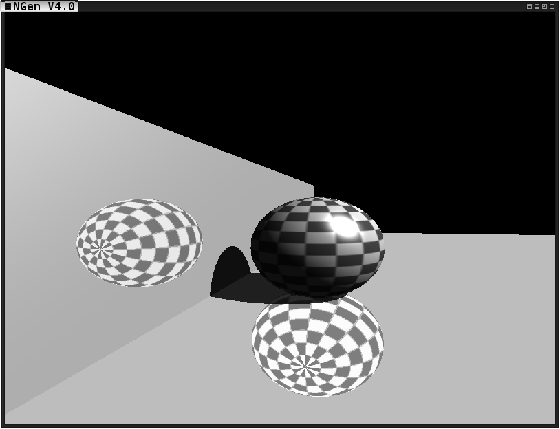
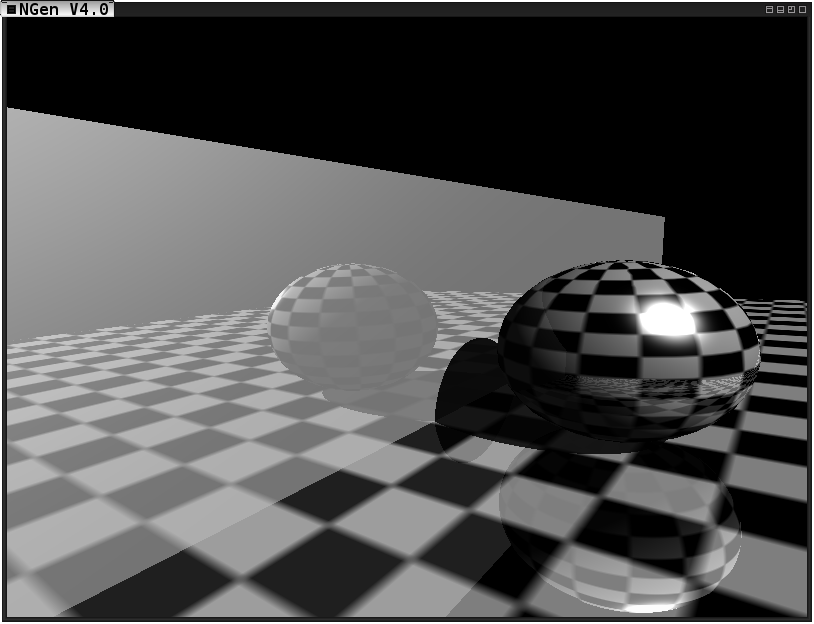
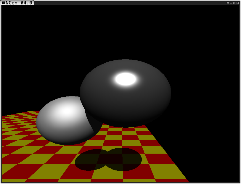
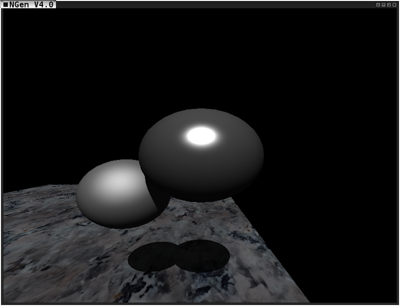
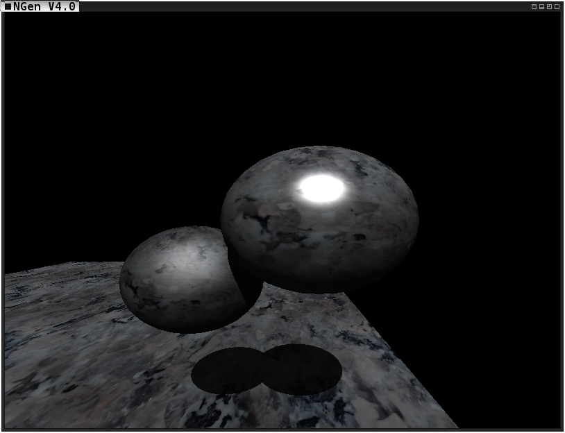
After a way-too-much fun spring break I am diving headfirst back into the grind this wonderful easter. The ray tracer now supports both procedural texture mapping, and texture mapping from an image! Enjoy some images of the progress.
A scene rendered with the ray tracer using procedural texture mapping on the floorA scene rendered with the ray tracer texture mapping the floor using an image of marbleA scene rendered with the ray tracer texture mapping the floor and the two spheres using an image of marble
I am also happy to report that the ray tracer is back to running in real time, and shadows can now be rendered from point lights as well. Furthermore, I’ve discovered I absolutely love OpenCL!
In my Alternative Interfaces & Physical Computing course I am currently in the process of designing a wearable project. I would like to create an instrument a user wears on their hands in the form of gloves. As somebody who both plays piano and programs as a hobby, I figured this would be a motivating project for me. In designing this project, I am effectively designing an experience I want the user to have while using my creation.
In the moments before using the instrument, I want my user to feel motivated to create music. As the user puts on the instrument he/she will feel the warm soft texture of the gloves, and upon touching anything, will have this motivation excited by the sound of notes filling the air. Of course, in order to be successful at playing an instrument, the artist will always feel a certain sense of focus and complete control.
While playing the instrument the user will get to experience the time, speed, and periodicity of the music they are creating. This will give a sense of power to the user as they are in control of all of those properties of the experience, and more. Each time the user feels the pressure of their fingers on a surface it will be coupled by the ringing of the corresponding note. This synergistic effect over multiple senses will give a more powerful effect to the music in the mind of the user in contrast to an audience. Depending on the chosen time, speed, and other audial properties of the playing, this instrument could produce a range of different emotions and responses by both the artist and audience.
After playing the instrument, I think the user should feel moved emotionally by the music that was played, this of course could vary greatly with what is being played. The user should also feel accomplished from their creation. Playing any instrument can also produce very therapeutic effects to the artist such as releaving stress among other things. I hope to have my instrument inflict all of these effects.
Some of the feelings I wish to leave users with include the following:
Accomplishment: The user, or artist, should feel accomplished after playing the instrument. He/she would have increased in skill level and could possibly have created a beautiful arrangement of sounds in the process. Depending on the case, I hope users are left with a moderate feeling of accomplishment.
Beauty: While at first this feeling may not be present, the hope is that after becoming proficient in playing the instrument an artist would be able to instill beauty in both the audience and him/her self. I am hoping to make the instrument create as much beauty as it is being used as possible.
Creation: Each time a user is using the instrument, they are in full control of the creation of (hopefully) beautiful arrangements of sounds. The instrument should be a way to play with building creativity. This will be a main focus of the instrument/experience.
Harmony: In playing the instrument, the user will be engaging both hands, and all ten fingers, in an extremely harmonious activity. When played correctly to create music the instrument will hopeflly leave the user with a moderate sense of harmony. This, of course, will only come with experience.
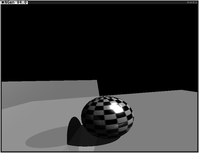
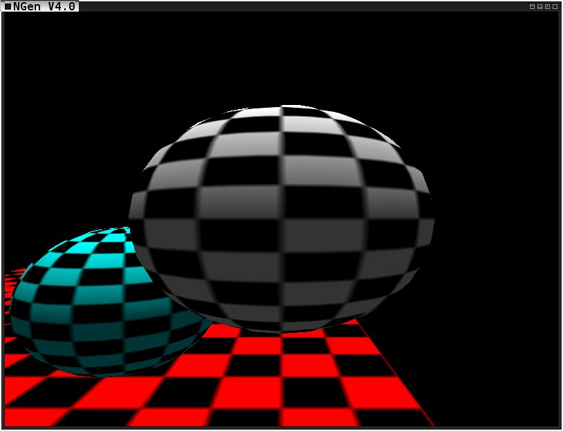
Recently in my Global Illumination course we were asked to implement basic phong shading into our ray tracer, aswell as complete the first shadow ray pass. Things went smoothly as far as implementing phong, however in performing the shadow pass I finally lost my real time framerate. With the shadow pass enabled my NGen only renders at 1-2 FPS for an 800x600 image. However, in light of this I have began learning OpenCL in preparations to implement the ray tracing algorithms using that. I will probably not be implementing the OpenCL calculations by before the next checkpoint. Instead I plan on working over the spring break to try and implement the ray casts in OpenCL.
But without further delay, here is the scene with shadows rendered in all of it’s glory:
A scene rendered with shadows depicting two spheres made of different materials
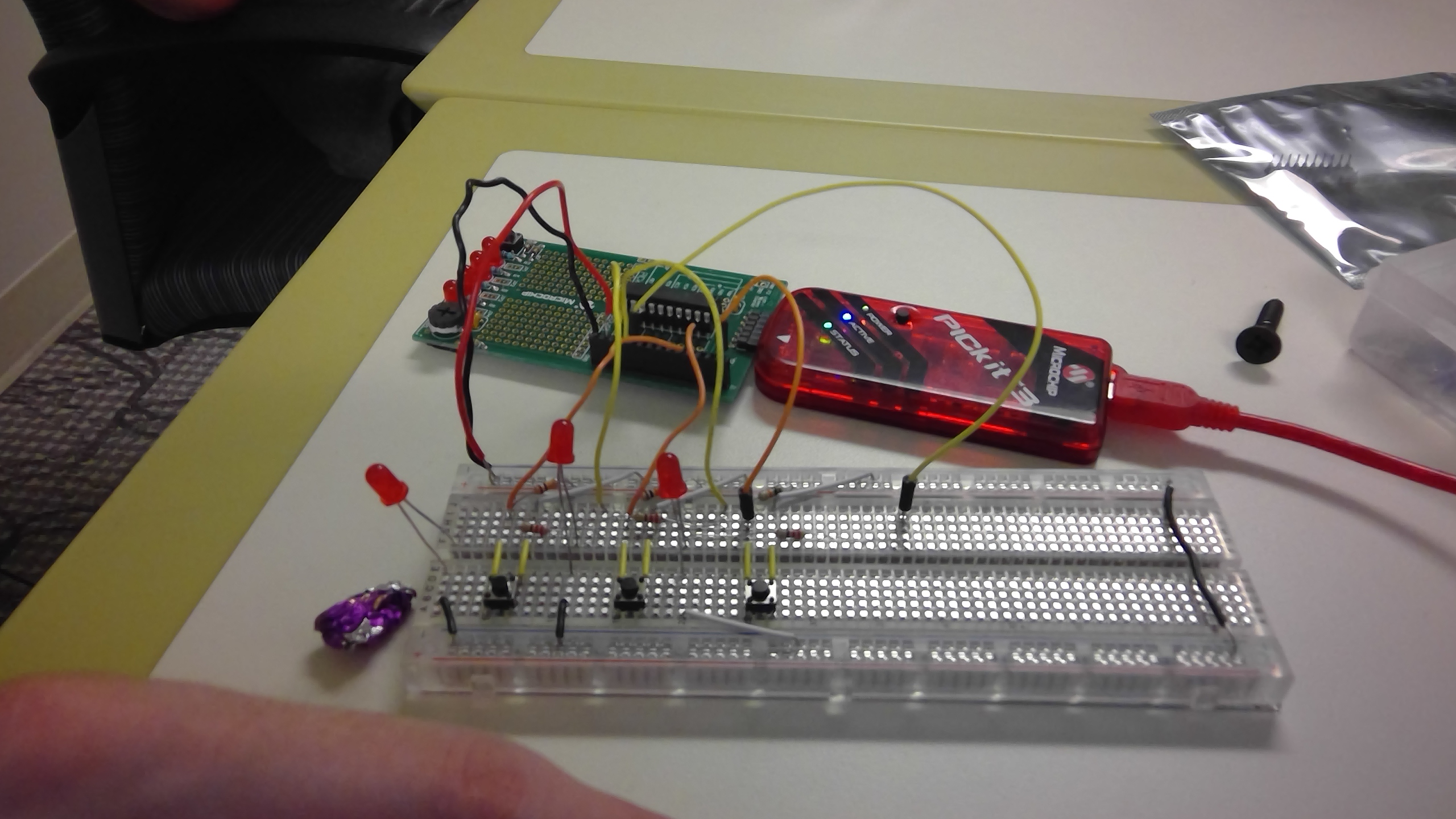
Recently I posted about a project proposal in one of my courses, Physical Computing and Alternative Interfaces. We had to create a project which used LEDs in some fashion. I decided to make a Simon Says game.
It game as no surprise most of my time was spent wiring and re-wiring, the actual programming was done relatively early. One thing that tripped me up a little more than expected was creating my own random number generator, and theres a lot of improvement which could be made. I completed mine by simulating a linear feedback shift register where the seed was based off of a timer value when recieving user input. The trouble is that the timer is set to update once per instruction cycle, which means that while I’m waiting for input the clock is incrementing by a fixed amount each time the loop executes to check the status of a switch. Unfortunately this lead to all seeds being a multiple of a number– and with only 8 bits & 3 possible outcomes to work with this causes extremely similar “random” patterns to be generated every single time. This could be fixed in the future by altering the clock register so that it is incremented based off of elapsed time rather than instruction cycles. Alternatively, allowing myself a larger amount of memory with which to randomize the bits while generating a random number could have also solved this problem. It is possible that just having more outcomes rather than only 3 possible LEDs could have given the perception of it being more random than it is.
Here is a picture of the completed circuit:
The completed Simon Says circuit
I took a video earlier, but it seems to have become corrupted.
The behavior of the game is as follows:
When switched on the game begins, first the user will be shown a pattern of 5 lights. Each light has a button in front of it that the user must press in the order the sequence was presented. If the user finishes the sequence correctly, the lights will flash from right to left 5 times in a quick succession. At this point the game begins again adding one random element to the existing sequence. If, however, the user enters the sequence incorrectly, upon the first incorrect key being pressed all lights will light up simultaneously for 3 long blinks- inturrupting the user. The sequence will then play again (but almost imperceptibly faster as a penalty) without adding an element.
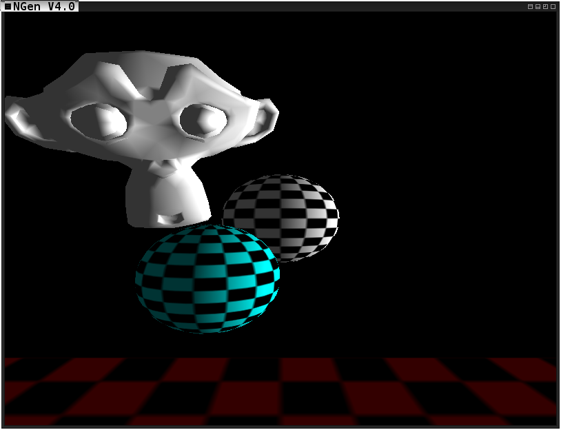
As the semester continues, so does the development of my Ray Tracer for my Global Illumination Class at Rochester Institute of Technology. As planned, I have been pursuing the development of a real time ray tracer to be implemented into my game engine, NGen. In order to make a real time ray tracer feasible, I will be beginning with a deferred rendering geometry pass, collecting information about the models projected onto the viewing plane in various textures. This information includes the world position, world normal, and diffuse color of the surface in each fragment. I will then use this information to cast the second set of rays for reflection, refraction, and shadows. The casts will incorporate spatial partitioning data structures as well as OpenCL as needed in order to maintain an acceptable frame rate. The results of these casts will then be stored in textures which will be sent to the lighting pass(es) of the deferred rendering pipeline.
This checkpoint contains the Ray Tracing framework which has the ability to cast rays in a given direction from an origin to determine what object they hit, the first point of intersection, the normalized minimum translation vector depicting the direction of smallest translation in order to decouple the intersecting objects, and the magnitude of overlap along this minimum translation vector. This checkpoint also contains the deferred rendering pipeline which I will be using to generate the images and effectively skip the first set of ray casts.
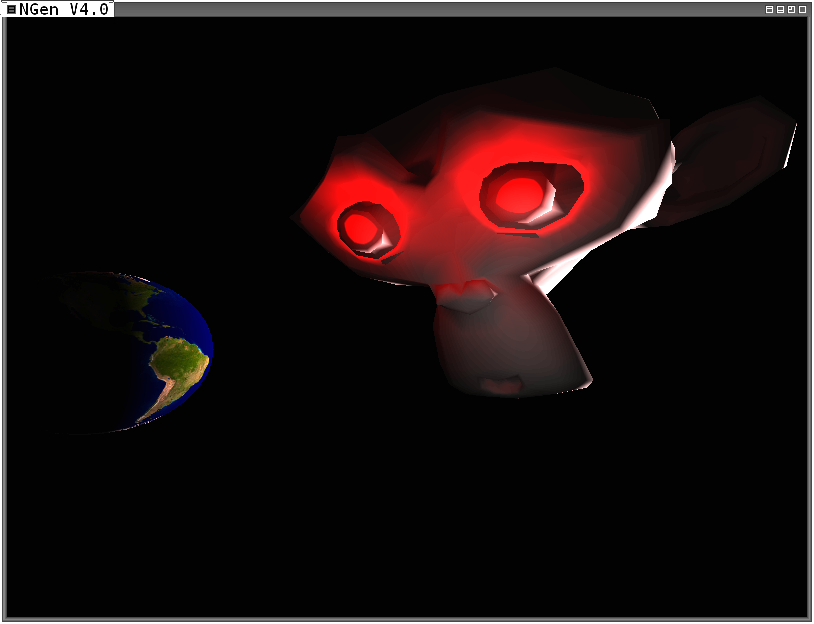
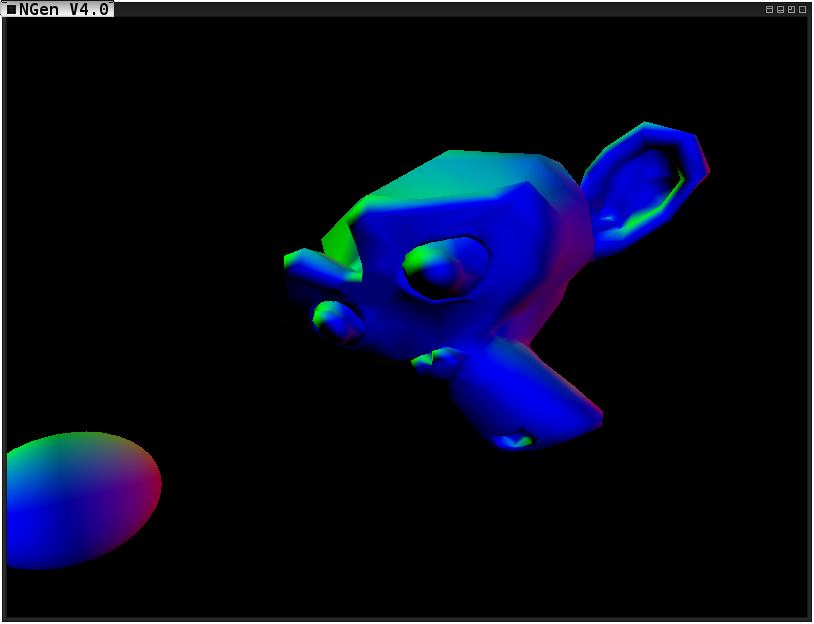
Below are some images either depicting progress or depicting me having fun doing what I do.
A scene rendered using a deferred rendering pipeline in NGen.The same scene rendered from a different angle.Suzanne, the Blender test model, joins the scene.Various point lights join the scene depicting one of the strengths of the deferred rendering pipeline.Suzanne threatens the earth in a way too dimly lit scene.The same scene as above, but colored based on the direction of the normals.
I am in this one incredible class this semester called Physical Computing and Alternative Interfaces. We focus on prototyping computing devices and systems with which humans can interact on a physical level. The first assignment, called Blink, requires you to build something using LEDs.
Having given my project a lot of thought, I decided that I want to make a Simon Says game. The game will contain N LEDs and N + 1 push buttons. When the “Start” button is pushed, a sequence of lights will light up. The user then needs to push the buttons positioned in front of the lights in the order which the corresponding lights lit up. If the user is correct, a single push will be added to the sequence and the next round will begin. If the user is incorrect, the sequence will play again, but all sequences will play faster from now on. Pushing the start button again will restart the game.
While a simple project, it will have a lot of components to manage. One thing I noticed in my projects is that I am not storing pins in variables, I always simply remember what goes where and access it with whatever factory name the data sheet says that pin is called. This project will focus on managing the components of the physical circuit in the code, as I have identified this as an area which I can improve.
I have returned from a long and uncalled for break. I’m hoping the second time around I will get into the habit of keeping this website updated with my latest endeavours- and here to help me do that are two new classes!
Since my last post my knee has healed, I have finished an amazing coop at GE Aviation, I have acquired a full time job, and I have learned so much. I have now returned to Rochester Institute of Technology for my final semester until I graduate with my BS in Game Design & Development. As apart of this semester, I am taking CSCI-711 Global Illumination, and IGME-470 Physical Computing and Alternative Interfaces. For both of these courses I am required to submit blog posts outlining my progress on two separate projects. It should be noted that I will now prepend any posts related to those courses with the course number stated above.
CSCI-711 Global Illumination, what’s that about huh? Well it’s this awesome course that teaches advanced computer graphics techniques to work towards more physically based rendering. This course takes the approach of teaching computer graphics by studying and modelling actual photography, cameras, and properties of light. Throughout the course I will be creating a ray tracer as well as developing a project which I will type more about soon!
IGME-470 Physical Computing & Alternative Interfaces, sounds interesting? Well it is! This course is all about bridging the gap between the digital and physical worlds through the use of microcontrollers and electronics components! The class uses arduinos to develop many different forms of physically interactive digital media. I am using this class as a way to learn embedded programming. I have asked my (awesome) professor if I could use PIC microcontrollers instead of an arduino or other preassembled prototyping board and she said yes! So I have been working with a PIC16F1829 with a PICkit3. I think soon I am going to pick up a few more chips and choose a simple straightforward one to work with this semester. The past few hours I have been struggling with Analog - Digital conversions, but I will get it!
In case you couldn’t tell I am extremely excited for these two classes. My semester is going to be my most busy yet- but I think I will also learn more than ever before. With 2 graduate level and 3 undergraduate courses my time will definitely be spread thin- and I’ll love every second of it.
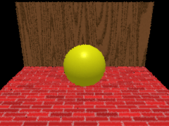
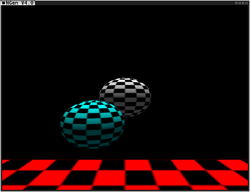
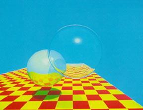
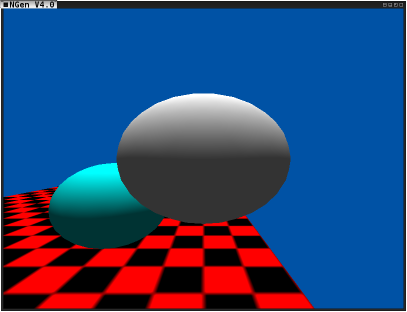
As I described previously, as a part of my Global Illumination course I will be building a ray tracer. The goal is to replicate the following image:
The scene my ray tracer should be able to replicate.
The first step to this assignment is to build the scene and log all of the positions, scales, and orientations of all objects (visible and invisible) in the scene. Below you will see my current rendering of the scene:
The target scene very basically rendered in my NGen.
The object transformations are as follows:
##Every object in the scene
- Orientation: Identity Matrix, every object is facing down the negative Z axis with the positive X on the right, and positive Y above.
It should be noted that although my camera is at the origin, the goal of my project will include an interactive camera to view the physical simulation.
Aswell as the objects transformations, one of my goals is to have the ray tracer run in real time while my NGen is still able to process user input, object state, physics, and collision management. If the ray tracer significantly slows down my NGen it could severely impact the integrity of the other systems (notably the physics and collision management). As a direct result, I decided it would be necessary to then log the physical properties of each object and record the desired behavior of the system to look back on as a control group.
The physical properties of the objects are as follows (Note: If a field is unspecified it is either 0 or the identity):
##Ground
- Inverse Mass: 0 //Thanks Ph.D. David Schwartz!
- coefficients of Friction (both): 0.5
- rolling resistance: 0
- constraints: freeze linear, freeze angular
##Large Sphere:
- Inverse Mass: .5
- coefficients of Friction (both): .1
- coefficient of restitution: 0.9
- rolling resistance: 0.1
##Small Sphere:
- Inverse Mass: 0.555555
- coefficients of friction (both): 0.08
- coefficient of restitution: 0.8
- rolling resistance: 0.1
Throughout my time in the Global Illumination course at RIT I will be working on a semester long project- this is the proposal for the project.
What?
I would like to build a real time ray tracer into my game engine, [NGen (www.github.com/MrNex/NGen)]. This ray tracer should be able to render a low-mid object dynamic scene while still processing input, collision detection, object state/behaviors, and physics. It should be noted that while this scope seems large, everything besides the ray tracer is already implemented.
Why?
As an undergraduate from the Game Design & Development program I have a strong interest in real time interactive applications. Furthermore, I have been devoutly working on NGen for ~3 years now and am currently on my third iteration of the project. One area of NGen I am still unsatisfied with is the rendering engine. The addition of a real time ray tracer could definitely fill that void!
How?
I plan to use the C programming language along with OpenGL and OpenCL as needed to achieve my goal. I will also use the libraries which are apart of my NGen or which my NGen depends on.
Who?
I, Nicholas Gallagher, would be working on this project alone.
Wish me luck!
Update!
Since this post the project has been completed. A new post containing links to the project, documentation, and a video can be found at the following link:
Link to a new post
My worst nightmare has finally come true. I’m actually in too much pain to program. On my way home from work Wednesday night I took a slam on my longboard. And by slam I mean my stomach hit a horizontal steel pole going very very fast. Shockingly enough- besides the bruises on my arms and stomach- it’s my knee that is hurt.
I managed to dislocate my Patella and tear a few ligaments and boy is it painful. All I can manage to do is sit here and stare at nothing. The last few days have been horrible- hopefully things will turn up from here. The real dread? The trip home I need to make tomorrow from Rochester NY back to Long Island..
My summer working as a researcher at Rochester Institute of Technology is coming to an end. I really enjoyed this job. It was pretty much the ideal work for me. I wish I had more time to keep on at this- it’s been amazing. I learned so many things and got so much practice doing what I love, but summer is coming to an end.
When one door closes another door opens. This fall I will be working at General Electric Aviation as a Software intern- I’m very excited. This will be my first time working for a big company such as General Electric. I’m looking forward to getting the feel of a larger atmosphere like that. However, I’m pretty nervous about one thing– that they are going to make the mistake of not using my talents to the fullest potential.
I’ve read a lot about Software Internship experiences at General Electric Aviation. The biggest complaint is that the interns don’t do any real work. Instead they get stuck with busy-work nobody else wants to do, like editing XML documents and what not. This makes me nervous for a few reasons- I hate web development, I hate busy-work, but most of all I would hate having the feeling of wasting time that I could have been at school studying.
Sure I will be getting paid pretty large sums of money, but to me knowledge is more valuable than any amount of money. I sure hope this opportunity at General Electric meets my expectations!
Along with finishing up one job and moving to another comes the whole routine of packing up and moving out. Boy is this stressful- while I’m trying to prepare for final exams and finish final projects for courses none the less! But one step at a time, eyes on the prize, soon I’ll have a week to relax and it’s off to my new apartment in Michigan! Time to get back to packing…
Like most studious academics, I unfortunately give a shit about my GPA. It’s a fault of mine, really, because it proves that I care what other people think about me. While yes, attaining the knowledge itself is most important, my GPA proves to the world that I have attained that knowledge. So forgive me, but I care.
Now don’t get me wrong; I am all for hard courses. I love a challenge. I am okay with getting a B in the course, especially when it’s just that difficult a topic. In that scenario, a B says I have certainly come a long way throughout the course even though I have not mastered such a difficult topic. But you better count on me continuing my studies in the area until I have! As a matter of fact, I think most courses I am subject to just aren’t difficult enough. I often feel the professors give too much leeway and that many of the grades given out weren’t truly deserved (yes, mine included in a few cases). This frustrates me for two reasons:
I feel my grade is less meaningful an achievement.
I feel the grade is a poor representation of my level of knowledge on the subject- and therefore difficult to use constructively.
However I’ve recently met the flip side of this scenario: a nit-picking nightmare grader of a professor who’s grades do not at all indicate my level of understanding of a topic.
Let me start by saying this: I do not dislike this professor. As far as his teaching style and demeanor go I really do enjoy him as a person. Even if he is so completely unapprochable and downright frightening and demeaning. Not to mention no help at all during office hours when he outright encourages students to come and see him and he will help them. But his grading is cruel. Let me break this down for you- the entire course grade is graded based on 4 projects and 3 examinations. Each project grade is graded out of 30 points, where 10 points are for meeting “Design Criteria” and 20 points are for passing test cases.
The test cases are graded strictly, but that’s not too big a deal. By strictly I mean if you accidently have a double-space after a period in the output and he doesn’t– you get 0 credit for that test case. This is totally fine though because he specifies exactly what he wants the output to be. Pain in the ass or not– it’s fair. However, let me clarify what he apparently means by “Design Criteria”. He means if anything in your entire program isn’t the way he likes it, you lose 33.3% of the entire project grade. Let me stress the fact that your program can pass every single test case and be designed to be extensible and modular but if he finds one thing wrong, 33.3% of your grade gone. Here’s an example of what I lost 33.3% of my entire project grades on: I did not check for an error which has absolutely 0% chance of ever happening. I approached him about this, kind of frustrated but moreso utterly confused and he told me, “That’s what is called a pre-condition check”, and I was SOL.
Mind you, in the documents he never said, “Check for this error”, he said, “It is an error if…”, which I absolutely agree with! That would have been a horrible error! It would have been a massive error on the programmers part! A massive error that when programmed correctly has no chance of ever happening. On every single project he has come up with something to dock off 33.3% of my grade. Each and every one literally comes down to ~6 words being added to the program.
The best part? The exams are graded with the exact same scrutiny.
For any professors out there reading this, please give grades that assess a students knowledge of a topic, not grades that are nit-picking just to spite them. And if you do want things perfect, I understand. A 100% should only be granted to perfect projects! But don’t knock them down to a 66.6% for something that is solved by:
ASSERT(i > count);
Especially when just prior to that is the equivilent of:
As many of you may or may not have read, I have been working in Research & Development under my professor Ph.D. David Schwartz at Rochester Institute of Technology this summer. I have been researching the most easily understood ways to implement various Game Physics topics, as well as developing a myriad of stand alone examples for fellow game developers to use as a resource or guide when implementing these topics. We currently have a lot of different examples, varying from ray tracing to 2D linear & angular collision resolution and this list is rapidly growing. Recently, my professor had went to a conference where he wanted to show what we were working on. My co-worker and I quickly moved a large quantity of the work to a Github repository where they are now publicly available for download. Those are not all of the examples, but there are quite a bit up there, and every day of the week we will be adding more (& more difficult) examples.
I will apologize in advance however, you must have visual studio to run the examples. This kills me inside, I would have loved to make these GCC compatible- but it would not have meshed well with the courses and faculty in my department at my school. Curses Microsoft! Restricting the audience of my work yet again!
So I said I came up with an algorithm for computing angular friction, and finally I tested it. At first I was unhappy with the results for reasons I can explain another time- but after a lot of thought (and reading a lot of papers about the physics of a top) realized that it is actually a correct & reliable way of computing discretized angular friction for motion that is about an axis normal to the surface.
Without further ado, the algorithm:
Determine the relative angular velocity between two objects which have collided (or are in a contact state).
By this I mean Obj2.AngularVelocity - Obj1.AngularVelocity
This would compute the relative angular velocity of Obj2 from the center of mass of Obj1.
Determine the normal force between the two objects to the surface.
If two objects collide they must each recieve equal and opposite reactions according to Newton’s laws of motion.
You can compute the magnitude of this normal force by taking the collision impulse between the two objects and performing the absolute value of the dot product of this impulse with the surface normal on the surface of collision/contact.
You only need the magnitude of the normal force because it’s direction is clear already (The direction of the surface normal).
Use the magnitude of this normal force to compute the static and dynamic magnitudes of friction (Much like the Coloumb model of friction).
These magnitudes are just going to be the respective coefficient of friction multiplied by the magnitude of the normal force.
Determine the magnitude of the relative angular velocity (1) in the direction of the colliding surface normal.
Again, just a simple dot product between the two vectors.
Determine the relative angular momentum of each object.
And the surface normal is the normal vector of the colliding surface
Do note that in the case of point - point / edge - edge collisions and etc. I use the Minimum Translation Vector calculated during the collision resolution step.
And don’t forget to calculate L2 aswell!
Determine & apply the frictional torque on each object.
If the magnitude of L# (5) does not overcome the value of the staticMagnitude (3) simply apply +- L# opposing the direction of intended motion.
By +- I mean “Plus or Minus”, determine which direction you must apply it to inhibit the angular motion. So in other words you may or may not need to scale L# by -1.
If the magnitude of L# (5) does overcome the value of the staticMagnitude (3) simply apply a vector in the direction of L#, but scaled to the magnitude of +- dynamicMagnitude (3) opposing the direction of intending motion.
Again, by +- I mean “Plus or Minus”, determine which direction you must apply it to inhibit the angular motion. You may or may not need to scale it by -1.
???
Profit.
On a more serious note, I really hope somebody might find this helpful. It took me a few tries to get this right. It seems like there exists an abundance of sources for the Coulomb Model of Friction but nothing talks about the angular case explicitly. I give all credit to Coulomb and his model. This work was completely derived from that.
The bitter sweet part about having a great job that you love is that it leaves little time for my great personal projects that I love, among other things I need to do. Namely, I wish I had more time to work on NGen, my 3D simulation engine. However, in what little free time I do have (that I have the willpower to keep working through) I have been working hard. Recently I reached a milestone (and closed a github issue) for removing all warnings from the NGen when compiling with gcc using the -Wall flag! Coming from a visual studio oriented code base this left my 16 thousand lines of code riddled with hundreds of errors, but finally they have all been squashed (and a few bugs were found in the process)!
Among those bugs I found a prevelant one in my computation of torque due to friction in the physics engine. To be frank, it didn’t at all work and coincidentally just appeared to be working for the given simulation. There seems to be a severe lack of understandable examples of computing torque due to friction in a physics engine, so I wrote my own algorithm! My algorithm is heavily based off of the Coloumb friction model. For anybody interested I will be posting a rundown of it here within the next week when I find the time.
Until then, be sure to check out the NGen, and keep on coding!
Yesterday ended my first week at my new job. I am currently working at Rochester Institute of Technology as a researcher & developer of the pedagogical sort. I am working under PhD. David Schwartz to research the best ways to teach the modelling of physical concepts through simulation, then I must develop concise and correct standalone examples demonstrating the modelling of the concept. During this development I must be very meticulous in documenting my program, not simply for the longevity of the code or the ease of following the logic, but to explain the mathematical and physics formulas, derivations, and (sometimes) proofs which allow us to model the concept in the way I am presenting. My work is to be distributed to my fellow students (and eventually (hopefully) the world) as a learning resource. For anybody interested, it is licensed under GPL and I will be working in my spare time on putting together a github repo to help with distribution.
I love my job. It is exactly what I want to be doing right now. I can turn my T-Swift up to 11 and write physics simulations all day! I learn so much researching the different ways of implementing a certain concept, I have uncovered a wealth of resources to help me develop simulations in future positions I may hold, and the working conditions are amazing. I have an unofficial desk in the Center for Advancing the Study of Cyber-Infrastructure in a room which contains 4 whiteboards. My desk has an alienware box under it sporting dual moniters with enough more than enough space to have my laptop up and running aswell. Dave lets me and my co-worker do our thing, create our own hours (within some reason), and have a lot of say over the direction of the project. Finally, because I want to become a professor later on in life, developing projects which fall right into my realm of interest as an educational resource for my friends and fellow students is basically a dream!
However, I decided I also wanted to take two classes while I was working this summer– that may have been a mistake. After this week I’m realizing how much work I signed up for. Before homework and addressing my basic human needs such as eating, cleaning, and sleeping I’m working 10.5 hour days. If you factor in the time it takes to cook a meal, eat it, and clean the dishes used It’s probably 11.5 - 12 hours. Then homework (and later projects) from two classes brings it to about 14-16 hours. Add another half for a daily shower. Then one of those classes gives two quizzes a week, so depending on the day thats another hour! My work & studies have finally completely consumed my life and it is exhausting. As exhausting as it is though, I do really enjoy what I do. I love to learn, program, math, and simulate. Even though I’m working my fingers to the bone I don’t think I’d have it any other way.
I just wish I had more time to work on this website and my NGen.
I must test whether or not these posts are working correctly. I am horribly inept at web development, and github is trying to make it really easy for me yet I still fail.
GitHub kindly decided to make it really really easy to host a developer blog (Or any other kind of site I suppose, for that matter)! As such, it would be a crime if I didn’t use it. The world is a small place, and with the advent of new technologies such as this it is quickly becoming smaller. To this I say, Hello World was a thing of the past when we couldn’t actually say hello to the entire world with the imperceptible movement of your finger, therefore Hello Universe, I am MrNex.